The clicking in the speaker when the μBITX transmit/receive relays operate can be annoying, especially if you are operating CW. More so if you enjoy wearing headphones while in that mode. The clicking does not go out over the air, just on the station speaker or ‘phones. If you bought the later version uBITX (version 4) then you won't have this problem and this modification isn't necessary. Otherwise, read on!
The reason for this noise stems from the simple design of the μBITX. The connection to the balanced modulator, which also serves as receive product detector, is shared by both the microphone preamplifier and the receive preamplifier. The appropriate circuit is powered from the switched TX and RX power busses which are controlled by the T/R relay (K1). Whenever one of these preamps is energized, the bias voltage charges the coupling capacitors and that impulse creates the popping noise.
This also occurred with the BITX40 and, after many experiments, I finally resorted to muting the audio during the period that the transitions occurred. The most effective method was to mute the LM386’s input amplifier section by grounding pin 7 before the receive-to-transmit transition and restoring it after the transmit-to-receive transition and gating the audio output before the sidetone insertion. It didn’t correct the problem completely, just made it more bearable.
The μBITX, of course, does not use the LM386. Rather it uses the TDA2822 and there is no easy method of internal muting. Shunting the input to ground introduces audio distortion even when it is not muted. A serial gate on the output had insufficient effect. Not one of the simple circuits that I tried were satisfactory.
Then I saw a suggestion from Wayne Cheng, VA7AT. That was the first solution that seemed sensible. He suggested rewiring the preamplifiers to be permanently powered and inserting serial gating in each of the inputs, controlled directly from the TX and RX power busses.
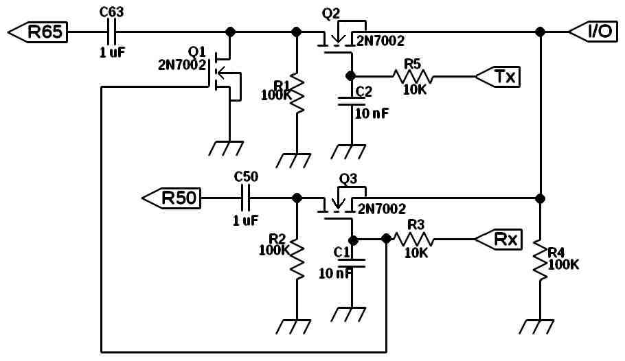
This modification, although the most complex of those that I tried, actually works! It only requires 12 components, all quite common, and costs less than 50 cents. It requires 2 traces to be cut and 2 small jumpers to be placed across traces. The new circuit is then connected using 6 jumpers from the new circuit board; The connection to the T7, 2 control inputs from the TX and RX busses, 2 outputs (one for the microphone preamp, one for the receive preamp), and a jumper to a common ground point.
Since I had all of the parts as surface mount I chose a small piece of single-sided printed circuit board, about 19mm by 19mm (3/4” X 3/4”) since a piece that size was already cut and appeared to be about the size that I needed. As this was a one-off prototype, I used my normal construction for SMD boards, cutting channels in the copper cladding with a knife. After checking for continuity, I smeared a film of solder over the conductive surfaces.
I mounted the components and then cut and attached the six jumper leads, cut from 28 AWG insulated hook-up wire, each initially about 5cm (2”) long. I strip one end of each, forming a 2mm (1/16”) inch right angle bend at the very end to facilitate solid soldering connections. These jumpers will be cut to length during installation.
If you don't feel like building this with surface mount, no worries! Since it is an audio circuit, layout and size are not critical. You can use through-hole parts. You can use island construction or perf-board if you want. Substitute 2N7000 or BS170 transistors.
Remove C50 and C63 from the uBITX board and solder them onto the new board. If you are using through-hole parts or polarized capacitors like elctrolytics or tantalum, be sure to be sure that the positive end faces the jumpers, the negative ends toward the drains of Q1, Q2, and Q3.
I scraped the coating from a short section of the TX trace (shown in the accompanying sketches) and used the knife to make a small cut across it to create an open. I checked that to insure that it was, indeed open, and tinned the exposed trace for the next step.
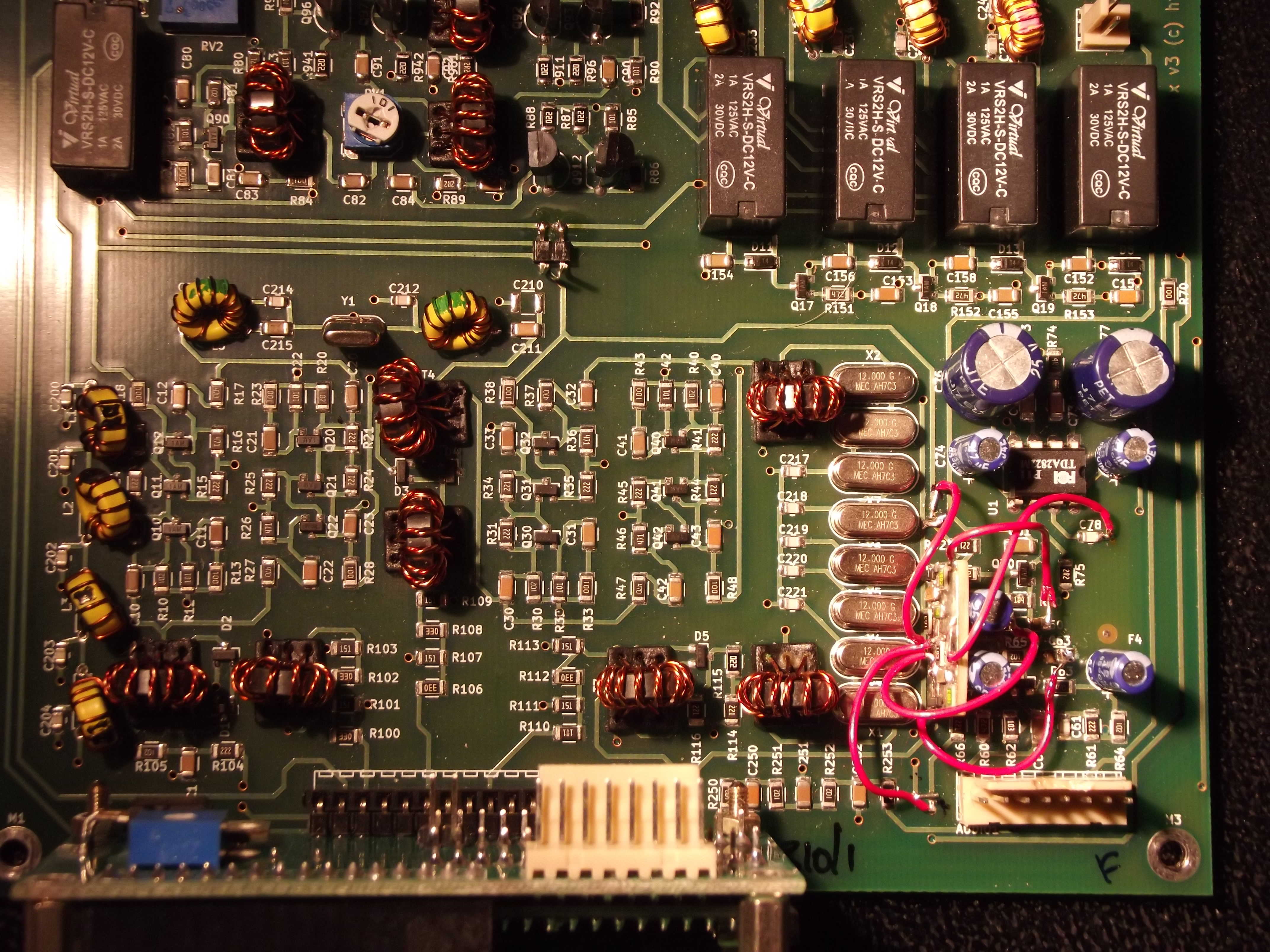
I prefer to use any nearby vias for modification jumpers. They make stable wiring points. Be sure to carefully remove enough coating to ease soldering. For small jumpers such as this project uses, I like to use the scrap wires that result from through-hole component installations. You know, those one or two inch leads on each end of a resistor or capacitor? Rather than toss them in a waste basket, I use one of those little plastic cups that single portions of apple sauce, diced fruit, or pudding comes in. Just the right size. I just reach in and grab an easily soldered wire. In this case, bend a small right angle bend in one end, drop it into the via hole and lay the rest across the target trace, where you prepared it by tinning. Use flush cut wire cutters to trim off any wire protruding beneath the board and to cut off the excess protruding past the trace leading to R66. The now isolated trace from the via is the source for the TX input to the new board so clean and tin the pad surrounding that isolated via and use that for the new connection. The microphone preamp is now powered by the 12 volt supply directly.
Since the nearest via on 12 volt buss to the receive preamp power is way up by X8, I just did without a via for the receive change. I prepared and cut the receive preamp power trace up from the bend in the area near X4 and X5, isolating R52. After removing the coating on the 12 volt trace, I soldered a small wire scrap across the two traces, thus connecting R52 to the 12 volt trace. The other side of that cut will then be the connection point for the RX input to the new board.
The common ground return will solder to the via at the end of C78, the other side of pin 7 of the audio output amplifier U1.
I cut the jumper leads from the new board to a length short enough to allow the board to be positioned on its edge with the bottom toward C52 and C64, the component side toward the row of crystals. This diminished the chance of accidental shorts and kept both the board and its jumpers below the level of the “AUDIO1” connector header.
CW operation is quite enjoyable now that the "pop" is gone. My wife is no longer annoyed with the constant popping when I check into a SSB net. Life is good!
de ND6T